ABSTRACT
This document analyzes the Mamba shield for Arduino with several experiments of powerlines communications over DC lines and AC lines. Principally, I’ve tried to guess the baud rate that this product can reach without transmission errors. INTRODUCTION
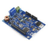
Power line communications technology is a way of carrying data on a conductor that can also be used for power transmission. You can use it to pass a control signal through the electrical wiring in a house for home automation. LinkSprite's Mamba shield gives your Arduino this ability. This Narrowband Powerline Communication shield can be controlled by your Arduino board using a simple SPI interface. From these places you can download the electric schematic, the codes and a step-by-step guide. The board needs to supply at least 1 Amp to work correctly. One of his inconvenient is that it needs a lot of caution if you use the board with high voltage.
The main element of Mamba shield is the PLM-1 modem. That chip is the brain of the board. It is a fully digital data transceiver for powerline communications using Frequency-Shift Keying (FSK) and it is designed to be controlled from an external Central Processing Unit, most commonly a microcontroller (MCU). Implementing the PHY and MAC layers of the OSI model, the PLM-1 provides a way to efficiently modulate and demodulate data packets. It features collision detection, as well as automatic forward error correction and CRC-16 data integrity verification. For more information, you can read the AC-PLM User manual that it can be downloaded from [3]. After this brief introduction, I explain the tests with this Arduino Shield.

This test is for seeing the change of the quantity of loss packet with different baud rates. The transmission code is running always and the loops are separated by a delay of milliseconds. The baud rate will be faster if the delay is less. The codes of the two Arduino with the Mamba shield are provided at the end of this review. The Appendix1has the transmiter code and the Appendix 2 has the receceiver code.
| 5 bits | 1 byte (0-255) | 61 bytes | 4 bits (CRC16) | |
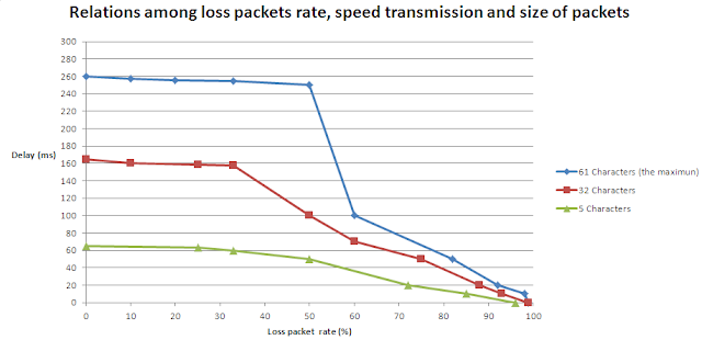
The next tables show the relations among the loss packet rate with different delays, size of packet and length of the wires. I’ve selected these delays because they are the points where the loss packet changes in the communications. The Table 2 shows the results with wires of 30 cm and the second Table 3 with wires of 250 cm. The column of characters means the number of bytes of a message without header and end of packets. The size of packet has influence in the loss packet rate.
| Mamba Shield connected by wires of 30cm | |||||
| 61 Characters (The maximum) | 32 Characters | 5 Characters | |||
| Delay (ms) | Loss packet rate (%) | Delay (ms) | Loss packet rate (%) | Delay (ms) | Loss packet rate (%) |
| 260 | 0 | 165 | 0 | 65 | 0 |
| 257 | 10 | 160 | 10 | 63 | 25 |
| 256 | 20 | 159 | 25 | 60 | 33 |
| 255 | 33 | 158 | 33 | 50 | 50 |
| 250 | 50 | 100 | 50 | 20 | 72 |
| 100 | 60 | 70 | 60 | 10 | 85 |
| 50 | 82 | 50 | 75 | 0 | 96 |
| 20 | 92 | 20 | 88 | ||
| 10 | 98 | 10 | 93 | ||
| 0 | 99 | 0 | 99 | ||
Table 2: Relations among loss packets rate, delays and size of packets with wire of 30 cm.
The data of the Table 2 are plotted in the graph below:

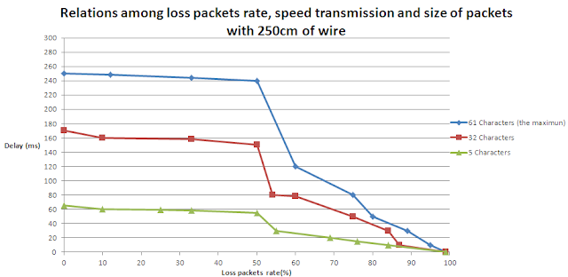
Now, the results of the same test with wires of 250 cm of length are in the Table 3.
| Mamba Shields connected by wires of 250cm | |||||
| 61 Characters (The maximum) | 32 Characters | 5 Characters | |||
| Delay (ms) | Loss packet rate (%) | Delay (ms) | Loss packet rate (%) | Delay (ms) | Loss packet rate (%) |
| 250 | 0 | 170 | 0 | 65 | 0 |
| 248 | 12 | 160 | 10 | 60 | 10 |
| 244 | 33 | 158 | 33 | 59 | 25 |
| 240 | 50 | 150 | 50 | 58 | 33 |
| 120 | 60 | 80 | 54 | 55 | 50 |
| 80 | 75 | 78 | 60 | 30 | 55 |
| 50 | 80 | 50 | 75 | 20 | 69 |
| 30 | 89 | 30 | 84 | 15 | 76 |
| 10 | 95 | 10 | 87 | 10 | 84 |
| 0 | 99 | 0 | 99 | 0 | 99 |
Table 3: Relations among loss packets rate, delays and size of packets with wire of 250 cm.
The data of the Table 3 are plotted in graph below:

The picture of the second experiment with wires of 250cm is shown beneath.

The conclusions of this test are these:
-The number of bytes in a packet transmitted has influence in the Speed Transmission Rate because with less number of bytes, the loss packet is less, hence, the delay in the transmitter code can be smaller.
-The length (short distances) of the wire has not influence in the Speed Transmission Rate because the loss packets are similar with wires of 30 cm and 250 cm.
APPENDIX 1

