
- Connect the camera, apply power and Ethernet cable:
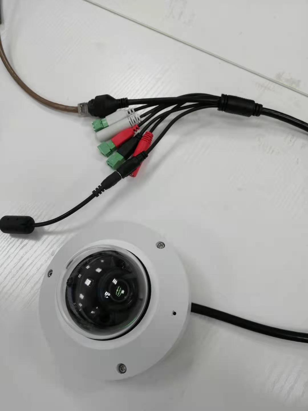
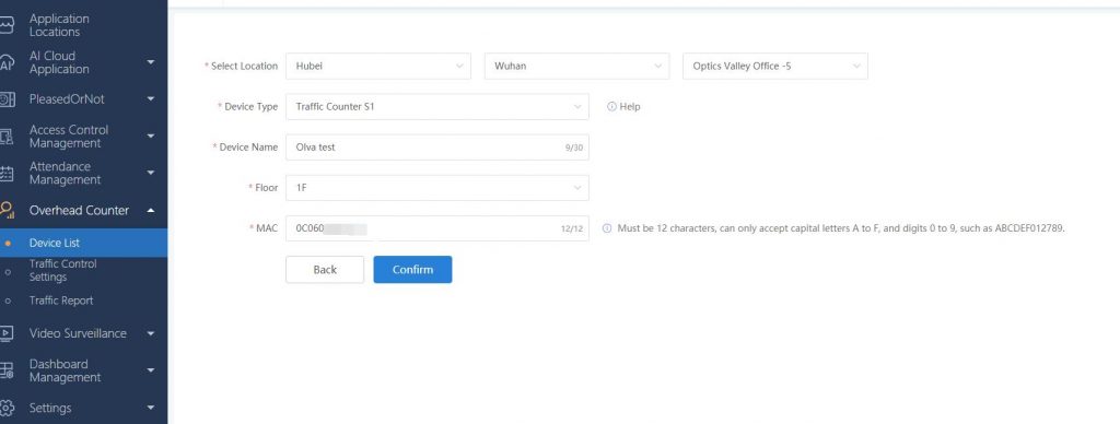
2. Connect the camera to deepcloud platform and log in to deepcloud platform (deepcloud.linksprite.com), click “Overhead Counter” — “Device List” — “Create New Device”, and fill in relevant information as required. The device MAC can be viewed on the label at the bottom of the device, as shown in the figure below:
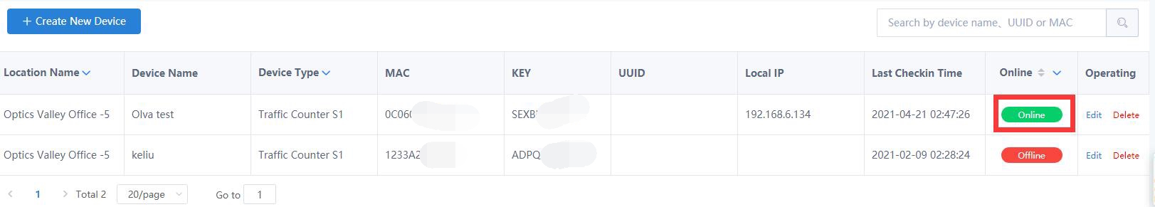
3. After the device is added, the device will be “offline”. Please restart the device and wait for a few minutes. The device will be “online”, as shown in the figure below:

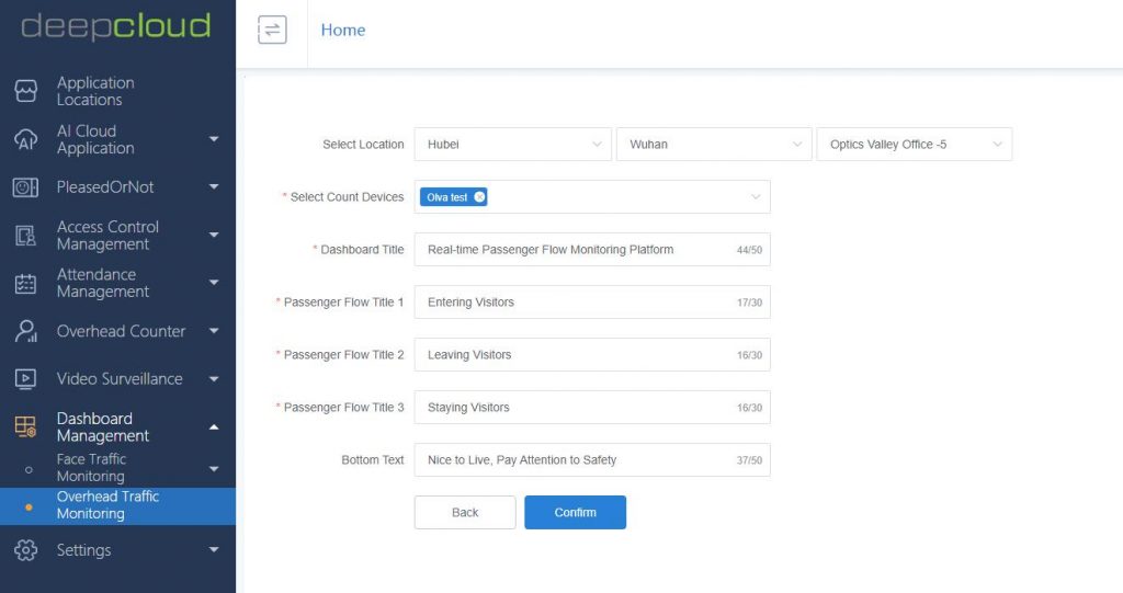
4. Click “Dashboard Management” — “Overhead Traffic Monitoring” — “Configure New Dashboard” to set the corresponding screen display information for the camera, as shown in the figure below:
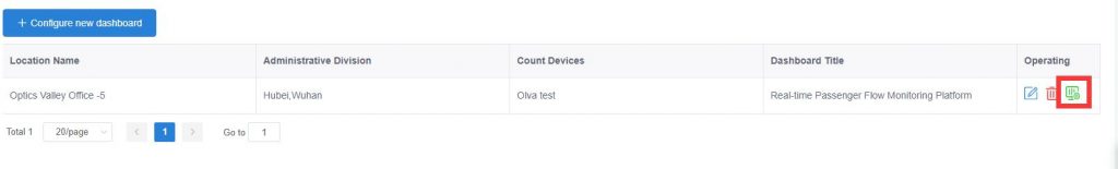
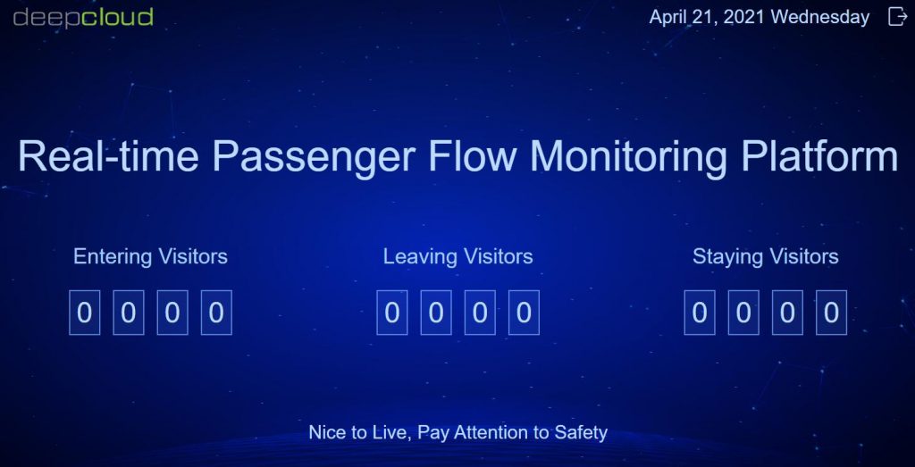
5. After the dashboard is configured successfully, as shown in the figure below, click the small icon on the right to view the screen display, as shown in the figure below:
LinkSprite provides a Windows tool to configure the head count camera. In the following section, we will show how to use the tool to configure the camera.
Configuration tools of People Counter Traffic Counting Overhead Camera
This tool supports the functions of device search, video screen preview, entrance direction setting, passenger flow statistics, restart cycle setting, entrance area setting, etc.
1. Device Search
The search function is only limited to the same network segment and cannot search across network segments. If there are multiple network cards on this machine, the search may fail and the redundant network cards need to be disabled.
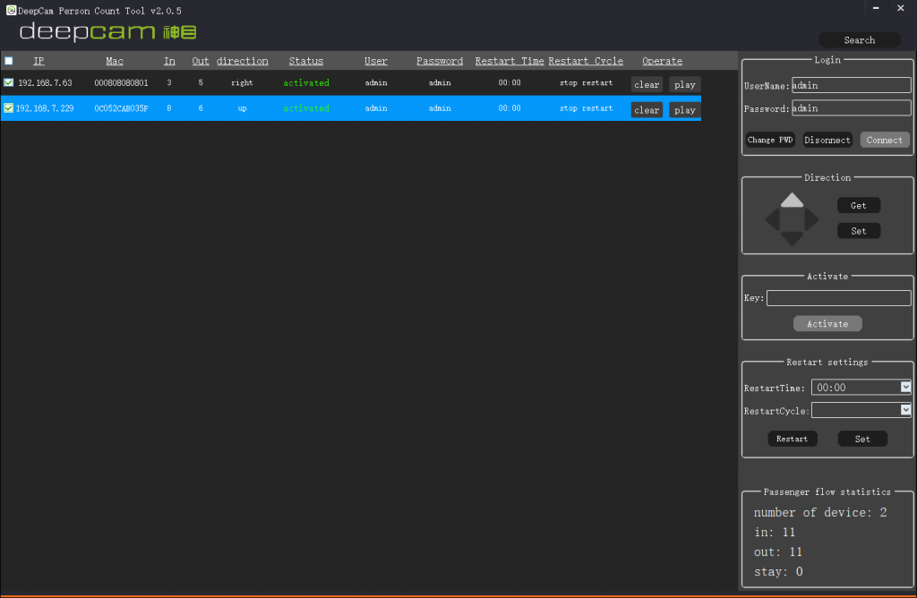
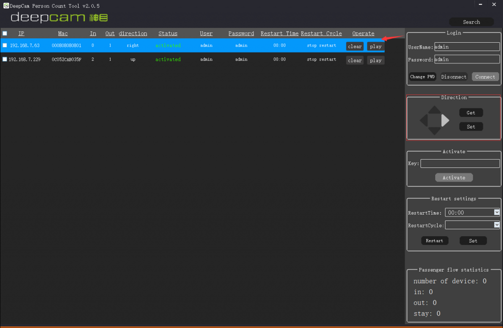
After clicking the search button, the device list on the left will display the searched device (as shown in the figure below). After the device is searched, the tool will automatically connect. The status column of the successfully connected and activated device will be displayed in green font. If it is not connected or activated, it will be displayed in red font. You can manually fill in the user name and password in the login area on the left The default user name and password are generally admin / admin.
For the inactive device, you can input the key in the “activate” area on the right to activate the device.

2. Entrance direction setting & entrance area setting
Entrance direction setting
Entrance direction setting function refers to setting the direction of passenger flow entering, and the opposite direction is the exit direction (the direction of passenger flow leaving). After selecting a device, the right direction area will automatically obtain and display the entry direction (as shown in the figure below). Users can select the entry direction in this area, and then click the set button to save the modification to the device. The get button can manually obtain the current configuration direction of the device, and the obtained direction results will be displayed on the direction button in time.
Entrance area setting
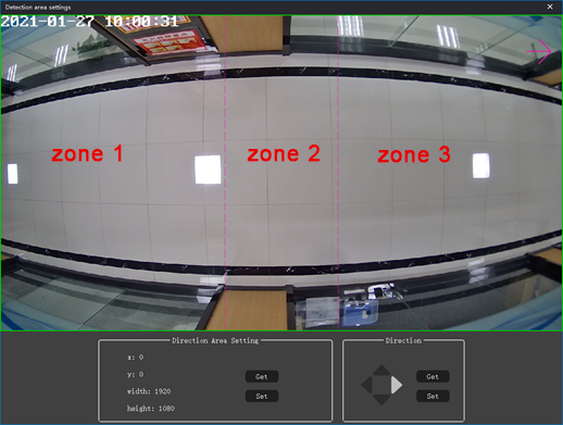
The entrance area is mainly divided into three parts, temporarily referred to as zone 1, zone 2 and zone 3, as shown in the following figure.

The area definition is defined according to the direction of entry. Only entering from area 1 and leaving from area 3 can be judged as an effective entry statistic. An effective exit statistic is entering from area 3 and leaving from area 1. Therefore, when setting the entrance area, we should try to meet this rule to ensure the accuracy of passenger flow statistics.
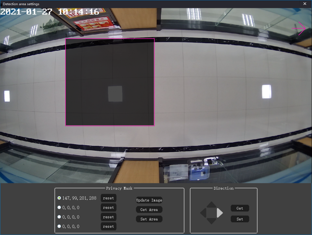
Mask area setting
Click the “set video mask” button at the bottom of the video preview page to enter the mask area setting interface. After setting the mask area, people in this position will not be detected. The tool supports setting up to 4 mask areas, as shown in the figure below. The mask area is black, and the left side of the mask area will be displayed at the bottom. After setting, you can click “set” At the same time, you can also click the “get area” button to synchronize the mask area configuration of the device to the local tool.
Passenger flow statistics
The in and out columns in the program list represent the number of people entering and leaving (as shown in the figure below). After checking the device, the comprehensive flow statistics of all the devices will be displayed in the lower right corner of the program, where in represents the number of people entering from the entrance, out represents the number of people leaving from the exit, and stay represents the number of people staying inside, The number of people displayed on the tool side will be updated from the device side in real time, with a delay of about 2-3 seconds. The “clear” button in the device list can clear the statistics of people flow reported by the device.