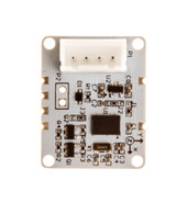
BNO055 board integrate 3 axis 12bit accelerometer and 3 axis magnetometer and 3 axis 16bit gyroscope together. Processing the data collected by the Cortex-M0 ARM processor. You can access the fusion data by programming (quaternions, Euler angle, rotation vector, etc.) can also obtain the original data (acceleration and angular velocity, magnetic field strength). Its data is transmitted through IIC bus to MCU.
Module pin
- VCC: Support 3.3 - 5.0V voltage input
- GND: Common ground
- SCL: IIC serial clock line pin, connected with the microcontroller IIC clock pin CLK
- SDA: IIC serial data wire pin, connected with the microcontroller IIC serial data
- INT: Interrupt the output pin that can be configured to trigger by a specific event, such as an accelerometer detects acceleration changes to produce an interrupt.
- RST: Reset pin
Hardware preparation
Arduino UNO x1
Linker Base Shield x1
Linker cable x1
Linker BNO-055 x1
Connect map
The BNO055 module can be connected with any micro controller with IIC communication function to carry out the communication. This experiment uses Arduino. And it easy to connect with Arduino, VCC and GND of BNO055 corresponding to power and GND of the board, SCL corresponding to the board of the IIC clock pin SCL/A5, SDA corresponding to the SDA/A4 IIC pin. As shown in Figure 1-1:
Testing phase
In the initial learning phase, you can go to download the necessary drive. Once downloaded extract to the Arduino libraries folder. As shown in Figure 1-2:
You can start the test after you add it
1.First
Double click arduino.exe software, open the routine which was just added. file->Example->Adafruit BNO055-1.1.3->sensorapi (here are four examples, we first select sensorapi)
As shown in Figure 1-3:
2.Second
Select the upper left corner of the compiler button to compile, just wait half a minute, it is ok.
As shown in Figure 1-4:
3.Next
click Tools->Board to select the development board model and paired serial number, we select mkII AVRISP at this test program, found from the device manager for serial port COM7.
As shown in figure 1-5:
4.Finally
now you can upload the compiled code to the Aduino. About half a minute later, the upload is successful, then open the serial port monitor, set the baud rate (9600). You can see the read data is displayed on the serial port.
The data changes can be found when you shaking sensor, the above data is processed through the data fusion algorithm. If you want to get the original data of a single sensor, you can directly use the original auxiliary function in the driver program, there are three main functions:
- getVector (adafruit_vector_type_t vector_type)
- getQuat (void)
- getTemp (void)
(a) getVector (adafruit_vector_type_t vector_type):
this function has only one input parameter vector_type, which indicates the type of the 3 axis vector data. Vector_type can be the following parameters:
- VECTOR_MAGNETOMETER
- VECTOR_GYROSCOPE (values in rps, radians per second)
- VECTOR_EULER (values in Euler angles or 'degrees', from 0..359)
- VECTOR_ACCELEROMETER (values in m/s^2)
- VECTOR_LINEARACCEL (values in m/s^2)
- VECTOR_GRAVITY (values in m/s^2)
For example, you want to get the VECTOR_MAGNETOMETER, you can open the rawdata in the example project, as shown in figure 2-1:
Find getVector () function from void loop() function, chang the parameter to VECTOR_MAGNETOMETER, as shown in figure 2-2:
Uploading after compiled. Open the serial port monitor, you can see the original detection data. As shown in figure 2-3:
(b) getQuat (void):
the function is to return a quaternion.
This part is in rawdata project, but it been shielded. You can find it in the loop void () function. Cancel the comments section, and comment the above vector part.
As shown in figure 2-4:
Uploading after compiled. Open the serial port monitor, you can see the original detection data. As shown in figure 2-5:
(c) getTemp (void):
This function returns the temperature of the current environment. In fact, you can find that you have seen the reading of the temperature in the serial port in (a) and (b). Here I do it again, to read the cycle of temperature data. GetTemp () function originally inside void setup(void) function. I first cut it to the loop void () function, and then Comment the other data read part of the loop () function out.
As shown in Figure 2-6:
Open the serial monitor, you can see the temperature data which is read cyclicity.
As shown in figure 2-7:


